Code P0340 appears when the engine control module (ECM) detects a malfunction in the camshaft position sensor (CMP) circuit. The sensor transmits the current camshaft position signal, which the ECM uses to synchronize fuel injection and ignition. When the signal is lost, distorted, or conflicts with data from the crankshaft sensor, the system stores the diagnostic trouble code (DTC) P0340 and activates the Check Engine light.
Let’s examine why the ECM makes this determination. With each engine revolution, the CMP sensor generates a series of pulses corresponding to the number of teeth on the camshaft reluctor wheel. The ECM compares these pulses with the crankshaft sensor signal and evaluates their correlation: timing between edges, pulse count per cycle, and phase alignment. If the CMP input signal is absent longer than a threshold period (usually above 600 rpm), interrupted, or does not match the expected pattern, the ECM records a fault condition and saves a freeze-frame snapshot of parameters at the moment the code was triggered.
It is important to understand that P0340 indicates a problem in the circuit, not necessarily the sensor itself. Wire breaks, oxidized connector contacts, short circuits to ground or power, or mechanical displacement of the reluctor wheel—any of these can cause the code even if the sensor is functional.
“Often the root cause is wiring or contacts. Service cases show such defects account for more than half of occurrences. Check power supply, ground, and harness integrity before replacing the sensor—this saves time and money.” – Daniel Brooks, automotive diagnostics and electronics specialist.
This information is general and does not replace professional consultation.
Page contents
Brief answer: what to do right now
Code P0340 signals a fault in the camshaft position sensor (CMP) circuit. Do not rush to replace the sensor. Initial steps: inspect the sensor connector, examine wiring, measure supply voltage and ground. Only after these checks should you test the sensor itself.
Is it safe to drive? Temporarily yes, if the engine starts and runs steadily. However, there is a high risk of sudden engine stall, power loss, and misfires. Schedule diagnostics as soon as possible.
Priority actions:
- Connect an OBD-II scanner, read codes, and record freeze-frame data.
- Check battery charge (voltage should be at least 12.4 V with ignition off).
- Inspect the CMP sensor connector and wiring harness for damage, corrosion, or breaks.
- Measure supply voltage and ground circuit resistance at the disconnected connector using a multimeter.
- Check the sensor signal with an oscilloscope (if available).
These steps will help localize the fault—electrical or mechanical—and avoid replacing good parts.
What does code P0340 (DTC P0340) mean?
P0340 is an OBD-II diagnostic trouble code indicating “Camshaft Position Sensor ‘A’ Circuit Malfunction.” The code is set when the ECM does not receive a valid signal from the camshaft position sensor (CMP) on bank 1, sensor “A.”
The CMP sensor monitors the angular position and rotational speed of the camshaft. The ECM uses this data to determine the timing of intake and exhaust valve openings, synchronizing fuel injection and ignition. Without an accurate CMP signal, the system cannot correctly identify cylinder phase, leading to engine operation issues.
The ECM sets code P0340 under the following conditions:
- Complete absence of CMP sensor signal while the engine is running (usually above 600 rpm).
- Intermittent signal—pulses disappear or appear erratically.
- Mismatch between CMP and crankshaft position sensor (CKP) signals—the correlation expected by the ECM is disrupted.
The code may be caused by electrical issues (breaks, shorts, contact corrosion), mechanical problems (damaged reluctor wheel, timing mark displacement), or software faults (rare ECM software glitches).
According to SAE J1979, the ECM must record freeze-frame data when the code is set: engine speed, load, coolant temperature, CMP/CKP correlation status. This data assists technicians in reproducing fault conditions and pinpointing the cause.
Symptoms of malfunction: how does code P0340 manifest?
When the ECM records code P0340, the vehicle continues to operate but with significant engine management issues. Symptoms vary depending on the fault nature: complete signal loss presents differently than intermittent signal.
Main signs:
- Check Engine light is on. Sometimes it flashes during severe misfires. A steady light indicates a stored code; flashing signals an active problem threatening the catalytic converter.
- Difficulty starting the engine, especially when hot or after long downtime. The ECM cannot accurately determine camshaft position and attempts to synchronize injection and ignition using crankshaft data alone, causing longer cranking and uneven starts.
- Engine stalls while driving. If the CMP signal is lost during motion, the ECM loses synchronization and enters limp mode. In some cases, the engine stops completely and requires an ignition cycle to restart.
- Unstable idle with fluctuating rpm. The ECM tries to adjust mixture and ignition timing based on indirect data, but without precise CMP input, adjustments lag. RPM may oscillate between 600 and 1000 rpm, causing engine shaking.
- Power loss and hesitation during acceleration. Due to injection and ignition timing mismatch, some cycles are inefficient. Acceleration feels sluggish, delayed, and sometimes jerky.
- Increased fuel consumption. Incorrect synchronization leads to incomplete combustion. The ECM compensates by increasing injection duration, raising fuel usage noticeably.
Symptoms may appear all at once or partially, depending on whether the signal is lost completely or intermittently.
How serious is code P0340 and is it safe to drive?
Code P0340 does not indicate immediate engine damage but should not be ignored. Without a valid CMP signal, the ECM operates with limited information, creating a chain of risks.
Risks when driving with P0340:
- Sudden engine shutdown. If the CMP signal disappears completely while driving, the engine stalls without warning. At speed, this is critical: brake booster vacuum is lost, steering becomes heavy (power steering assist may be lost). Accident risk increases significantly.
- Increased fuel consumption. Incorrect timing causes fuel wastage, increasing costs and stressing the catalytic converter with unburned fuel.
- Catalytic converter damage. Misfires send raw fuel into the catalyst, which burns at high temperature, causing overheating and damage to the substrate. Replacing the catalytic converter is much more expensive than diagnosing the CMP sensor.
- Risk of valve-to-piston contact (for interference engines). If P0340 is related to timing mark displacement (chain stretch, belt jump), valve timing is disrupted. In interference engines, valves may collide with pistons, causing bent valves, damaged pistons, and costly repairs. This risk depends on engine type; verify your vehicle’s engine design.
Is it safe to drive?
Short-term yes, if symptoms are mild: engine starts, idles without stalling, responds to throttle. Avoid sudden acceleration, passing, and high-speed highway driving. Plan the route to reach a repair shop or home garage as quickly as possible.
If the engine stalls repeatedly, runs roughly, or the Check Engine light flashes, call a tow truck. Continuing to drive is unsafe.
| Scenario | Risk | Recommendation |
|---|---|---|
| City, short trips (<6 miles / 10 km) | Medium | Driving allowed with caution; diagnostics within 1–2 days |
| Highway, speed >50 mph (80 km/h) | High | Not recommended; risk of engine stall at speed |
| Repeated engine stalls | Critical | Tow truck; do not drive the vehicle |
| Fluctuating idle but engine keeps running | Medium | Driving to a repair shop allowed; avoid heavy loads |
This information is general and does not replace professional consultation.
Important note: P0340 is often accompanied by related codes—P0335 (crankshaft sensor), P0341 (CMP signal out of range), P0016–P0019 (timing correlation faults). If multiple codes appear simultaneously, prioritize checking power supply, ground, and CMP/CKP signal correlation. The issue may lie in a shared circuit rather than a specific sensor.
Main causes of code P0340
Code P0340 can be caused by faults anywhere in the chain: sensor → wiring → ECM → mechanical timing components. Below is a ranked list of causes by frequency based on analysis of technical sources and diagnostic reports from 2024–2025.
- Camshaft position sensor (CMP) failure—common cause.
- Wiring, contacts, and connector issues—also frequent.
- Contamination or damage to the reluctor wheel—less common.
- Timing phase misalignment (chain stretch, belt jump, tensioner wear)—less frequent.
- ECM or software malfunction—rare.
Most faults involve the sensor and wiring. Mechanical and software causes are less common but more complex to diagnose.
Let’s examine each cause in detail.
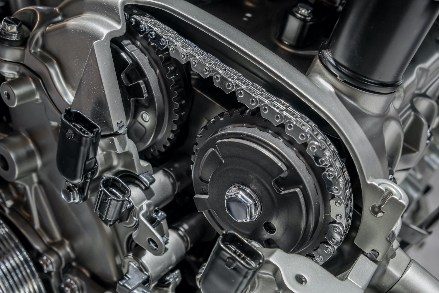
Camshaft position sensor (CMP) failure
The CMP sensor may fail internally due to coil breakage (for inductive sensors), Hall element short (for Hall sensors), electronics degradation from overheating, mechanical damage to the housing, or contamination of the sensing area with metal shavings or oil.
Typical failure scenarios:
- Internal break. No signal output. The ECM sets P0340 at the first synchronization attempt (usually above 600 rpm). A multimeter shows infinite resistance between terminals or no voltage change when rotating the shaft.
- Internal short. Signal present but distorted: voltage level does not reach the upper threshold (around 5 V for Hall sensors), or pulse frequency is erratic. An oscilloscope shows missing pulses, noise, or unclear edges.
- Overheating degradation. Sensor works on a cold engine but signal disappears after warming up. Common for sensors near the exhaust manifold or under the valve cover without sufficient heat dissipation. Overheating damages semiconductor elements inside Hall sensors or insulation in VR sensors.
- Contamination with metal shavings. Shavings from camshaft or lifter wear adhere to the sensor’s magnetic part, causing interference. Signal becomes intermittent; the ECM records P0340 or P0341 (signal out of range).
How to test the sensor:
- Disconnect the sensor connector.
- Measure resistance between signal and ground terminals (for inductive VR sensors, normal is typically 300–1200 Ω; for Hall sensors, infinite as they have no coil).
- Connect an oscilloscope to the signal line and start the engine. A good sensor signal should be:
- Hall sensor: square pulses with sharp edges, amplitude 0–5 V, frequency proportional to engine speed.
- VR sensor: sinusoidal pulses, amplitude increasing with rpm (from about 1 V at idle to 10+ V at high rpm).
- Compare the CMP waveform with the crankshaft sensor (CKP) signal. Correlation should match manufacturer specifications (for example, on some 4-cylinder engines, 1 CMP pulse per 2 crankshaft revolutions).
If the sensor produces no signal or a distorted signal with correct wiring and power, replacement is required.
Before installing a new sensor:
- Clean the mounting surface of oil, dirt, and metal shavings.
- Inspect the reluctor wheel on the camshaft: teeth must be intact, not chipped, deformed, or covered with deposits.
- Install the sensor, tightening the mounting bolt to the specified torque (typically 71–106 lb-in. / 8–12 N·m; check the manual).
- Check the gap between the sensor and reluctor wheel (critical for some models; typical range 0.008–0.059 in. / 0.2–1.5 mm depending on type).
After replacement, clear the code, start the engine, check the waveform, and ensure P0340 does not return.
Wiring damage or poor contact in the sensor circuit
Wiring and connectors are the weakest link in the CMP circuit. The harness runs in the engine bay, exposed to vibration, temperature changes, oil, moisture, and road chemicals. Over time, insulation cracks, contacts oxidize, and wires break.
Typical damage points:
- Sensor connector. The plastic housing becomes brittle from heat and cracks. Moisture enters, contacts oxidize (green copper oxide). Contact is interrupted, and the ECM sets P0340.
- Wiring harness near engine entry. The harness often passes near the exhaust manifold or timing cover. High temperature damages insulation; engine vibration rubs wires against metal brackets. Wire breaks may be hidden: the wire looks intact but is internally broken.
- Power or ground circuit break. If the power line (+5 V or +12 V depending on sensor type) is broken, the sensor does not work at all. If ground is broken, the signal fluctuates, and the ECM sees erratic pulses.
- Signal line shorted to ground or power. The ECM sees a constant low (short to ground) or high (short to +12 V) level instead of pulses. Codes P0340 or P0341 appear.
How to check wiring:
- Disconnect the sensor connector.
- Turn on the ignition (do not start the engine).
- Measure supply voltage at the connector pin on the harness side (not the sensor side). For Hall sensors, normal is about 5 V; some VR sensors have different circuits (check the manual).
- Measure ground circuit resistance from the connector ground pin to the battery negative terminal. Normal is less than 1 Ω. Higher indicates a break.
- Continuity test the signal line from the sensor connector to the ECM pin (requires a wiring diagram). Resistance should be under 5 Ω. Infinite means an open circuit; near zero with the sensor disconnected may indicate a short.
- Check insulation resistance: measure resistance from each wire to vehicle ground with the sensor and ECM disconnected. Normal is above 10 kΩ. Lower indicates insulation failure.
Wiring repair:
- Clean oxidized contacts with contact cleaner or a suitable terminal-cleaning tool. Apply dielectric grease around the connector seal area, not on the terminal contact surfaces.
- For broken wires, strip the ends 0.39 in. (10 mm), twist, solder with rosin-core solder, and cover with heat-shrink tubing. Do not twist wires together without a proper repair—connection reliability will be poor.
- If the harness is worn in multiple places, replace the section or entire harness.
- Protect repaired sections with split loom or heat-resistant tape, and secure with clips to avoid contact with hot or moving parts.
After repair, check resistance and voltage drop under load (start the engine, measure voltage at the sensor pins—it should not drop below normal).
Engine control module (ECM) malfunction
ECM faults causing P0340 are rare but should not be excluded, especially if all other checks are clear.
Typical ECM failure scenarios:
- Input driver damage. The ECM contains a CMP signal processing circuit (comparator, pull-up resistor, protection diode). If damaged (for example, by a voltage spike from reversed battery polarity or jump-starting), the ECM does not see the sensor signal even if the sensor and wiring are fine.
- Capacitor degradation on the ECM board. Electrolytic capacitors dry out over time, losing capacitance and affecting internal power stability. Symptoms include intermittent trouble codes appearing and disappearing.
- Firmware or calibration errors. Rarely, after software updates or calibration changes (performance tuning, emissions-related modifications), the ECM misinterprets the CMP signal, causing P0340 despite a physically sound system.
- Intermittent ECM connector fault. Oxidized or loose ECM connector pins cause signal interruptions during vibration, triggering the code.
How to diagnose the ECM:
- Check ECM power and ground. Voltage at the main power connector must be stable; ground resistance less than 0.5 Ω.
- Check input voltage at the CMP signal pin. If no voltage changes during cranking but the sensor signal exists, the problem is wiring between the sensor and ECM or the ECM input circuit.
- If possible, substitute a known-good ECM. If P0340 disappears, the original ECM may be faulty.
- Update ECM firmware to the latest version through a dealer or qualified repair facility. Manufacturers sometimes release updates that address sensor signal processing issues.
Important: ECM work without specialized equipment and knowledge is risky. Unsuccessful soldering or reflashing can irreversibly damage the unit. Trust ECM diagnostics and repair to professional shops or automotive electronics specialists.
Step-by-step DIY diagnosis of code P0340
This information is general and does not replace professional consultation.
Diagnosis of P0340 follows the principle “from simple to complex”: first check electrical components (basic tools), then mechanical parts (requires removing covers), and finally the ECM and firmware.
Required tools:
- OBD-II scanner with Live Data and Mode
$06support (advanced diagnostics). - Multimeter with resistance and voltage measurement functions.
- Two-channel oscilloscope (optional but highly recommended for precise CMP/CKP signal analysis).
- Basic set of wrenches, screwdrivers, and connector removal tools.
Step 1: Visual inspection
Start with an external inspection. Open the hood, locate the camshaft position sensor (usually mounted on the cylinder head near the timing cover or under the valve cover). Check:
- Sensor connector. Ensure the plug fits tightly, with no cracks in the housing and no moisture or corrosion on the contacts. Disconnect the connector and inspect the pins—they should be clean, without green oxidation.
- Wiring harness from the sensor. Trace its path to the ECM or an intermediate connector. Look for abrasion, breaks (a wire may look intact but feel brittle when bent), and insulation melting.
- Sensor mounting. The mounting bolt should be tight. A loose sensor causes an incorrect gap to the reluctor wheel, leading to signal loss.
- Oil leaks. Oil on the sensor or connector can cause shorts or contaminate the sensing area.
If obvious defects are found (broken connector, wire break, oil contamination), fix them and check if the code disappears.
Step 2: Reading codes and freeze frame
Connect an OBD-II scanner to the vehicle’s diagnostic port (DLC). Turn on the ignition (do not start the engine). Read trouble codes:
- P0340 confirms a CMP circuit fault.
- Related codes: P0335 (crankshaft sensor), P0341 (CMP signal out of range), P0016–P0019 (timing correlation faults). If multiple codes are present, prioritize checking common power and ground circuits.
Read freeze-frame data—a snapshot of parameters at code occurrence: engine speed, load, coolant temperature, CMP/CKP correlation status. Record this data to help reproduce fault conditions during a test drive.
Check Live Data (real-time parameters). Start the engine and observe:
- RPM from CMP and CKP sensors—should match actual engine speed.
- Timing advance—not zero or in a fault range.
- Fuel trim—if excessively high (>15%), it may indirectly indicate synchronization issues.
If the scanner supports Mode $06, check CMP signal dropout counters and failure statistics. High counts confirm the problem.
Step 3: Power and ground check with multimeter
Disconnect the CMP sensor connector. Turn on the ignition (do not start the engine).
- Power supply. Measure voltage at the power pin on the harness side of the connector. For Hall sensors, normal is about 5 V (±0.5 V). Some inductive VR sensors do not have a power supply—they generate signals themselves.
If voltage is missing or significantly low, check wiring from the ECM, fuses, and relays. - Ground. Measure resistance from the ground pin on the connector to the battery negative terminal. Normal is less than 1 Ω. Higher indicates a break or poor contact.
- Circuit integrity. Continuity test the signal line from the sensor connector to the ECM pin (requires a wiring diagram). Resistance should be under 5 Ω. Infinite means an open circuit; near zero with the sensor disconnected may indicate a short to ground or power.
- Sensor resistance. Measure resistance across the sensor terminals (disconnected sensor or on the vehicle with the connector unplugged).
- For inductive VR sensors: normal is typically 300–1200 Ω (check the manual for the exact value).
- For Hall sensors: infinite resistance between signal and ground (no coil).
If readings deviate significantly, the sensor is faulty.
Step 4: Signal check with oscilloscope
If the multimeter shows no issues but the code persists, use an oscilloscope for precise signal analysis.
- Connect channel 1 of the oscilloscope to the CMP sensor signal line (backprobe the connector or use an appropriate test lead).
- Connect channel 2 to the crankshaft sensor (CKP) signal for correlation comparison.
- Ground the oscilloscope to battery negative or the engine block.
- Start the engine and let it idle.
What to look for on the waveform:
- Hall sensor: square pulses with sharp edges, amplitude 0–5 V. Missing pulses, noise, or fluctuating amplitude indicate sensor or wiring faults.
- VR sensor: sinusoidal pulses with amplitude increasing with rpm. At idle (~800 rpm), amplitude should typically be at least 1–2 V. Lower amplitude or distorted shape indicates a weak sensor or excessive gap.
- CMP/CKP correlation: For 2 crankshaft revolutions (720°), one camshaft pulse (360°) may appear on some 4-cylinder engines. If the ratio is off, mechanical timing issues (mark displacement, chain stretch) are likely.
Save the waveform and compare it with reference patterns from service information for your vehicle model.
Step 5: Timing mark inspection
If the sensor signal exists but correlation with the crankshaft is off, check valve timing alignment.
- Remove the timing cover (belt or chain drive).
- Rotate the crankshaft to top dead center (TDC) of cylinder 1. The crankshaft pulley mark should align with the block or front cover mark.
- Check camshaft sprocket marks. They should align with marks on the cylinder head or timing cover.
If marks do not align (shifted by 1–2 teeth or more), the chain is stretched, the belt has jumped, or previous timing service was incorrect. Timing adjustment or replacement of the timing set is required.
Step 6: Final test
After fixing defects (sensor replacement, wiring repair, timing correction):
- Clear the code with a scanner.
- Start the engine and warm it to operating temperature.
- Perform a test drive replicating freeze-frame conditions (rpm, load).
- Read codes again. If P0340 does not return, the issue is resolved.
How to fix code P0340: repair methods
After diagnosis, choose the repair method based on the identified cause. Below is a systematic overview with complexity, tools, time, and risks.
| Method | Complexity | Tools | Time | Risk | When to apply |
|---|---|---|---|---|---|
| CMP sensor replacement | Low | Wrenches, ratchet, connector tool | 30 min | Connector damage during installation | Confirmed sensor failure (oscilloscope/multimeter test) |
| Wiring repair/contact cleaning | Medium | Multimeter, soldering iron, heat-shrink tubing | 1–2 hours | Short circuit due to poor soldering | Detected breaks, corrosion, or harness damage |
| Timing set correction/replacement | High | Service information, special timing tools | 2–6 hours | Engine damage from incorrect installation | Timing mark displacement, chain stretch, belt jump |
| ECM update/repair | High | Scanner, manufacturer software | 2+ hours | Irreversible software failure, loss of calibrations | Confirmed ECM hardware/software fault |
CMP sensor replacement
Sensor selection:
- Use the vehicle VIN to select the exact OEM part number. Sensors differ by type (Hall/VR), number of pins (2 or 3), and connector shape.
- OEM sensors are preferred, but quality aftermarket brands (Bosch, Delphi, Denso) are acceptable. Avoid no-name copies—they have low durability and may not meet ECM calibration requirements.
Replacement procedure:
- Turn off the ignition and disconnect the battery negative terminal for safety.
- Disconnect the sensor connector. Remove the mounting bolt (usually one bolt, 8–10 mm socket).
- Remove the old sensor. Clean the mounting surface of oil, dirt, and metal shavings. Inspect the reluctor wheel teeth for damage.
- Install the new sensor and tighten the bolt to 71–106 lb-in. (8–12 N·m) (check the manual). Do not overtighten to avoid cracking the sensor housing.
- Check the gap between the sensor and reluctor wheel (if adjustable). Typical gap: Hall 0.008–0.020 in. (0.2–0.5 mm), VR 0.020–0.059 in. (0.5–1.5 mm). Use a feeler gauge.
- Reconnect the connector and make sure the locking tab clicks.
- Reconnect the battery, clear codes with a scanner, and start the engine.
Post-replacement check:
- Use an oscilloscope to verify the signal waveform at idle and up to 2000–3000 rpm.
- Check CMP/CKP correlation.
- Perform a 6–9 mile (10–15 km) test drive, then rescan for codes.
If P0340 does not return, replacement was successful.
Wiring repair and contact cleaning
Work procedure:
- Disconnect the sensor connector and ECM connector (if accessible).
- Clean oxidized pins in connectors with appropriate terminal-cleaning tools. Be gentle—contacts are thin.
- Apply dielectric grease to the connector seal area to protect against moisture and corrosion. Do not apply it on the terminal contact surfaces.
- For broken wires: strip 0.39 in. (10 mm), twist, solder with rosin-core solder, cover with heat-shrink tubing, and heat. Do not use electrical tape alone—it loosens with vibration and heat.
- If the harness is worn in multiple places or near hot parts, replace the section or entire harness if cost-effective.
- Route the harness away from the exhaust manifold, moving engine parts, and sharp edges. Secure with clips to fixed points.
Post-repair check:
- Continuity test wiring with a multimeter—signal and ground resistance should be normal.
- Measure voltage drop from the sensor connector to the ECM under engine load. Power drop <0.2 V, ground drop <0.1 V.
- Start the engine and gently move the harness at repair points—the signal should remain stable.
Timing set correction/replacement
If timing marks are misaligned or the chain/belt is stretched, mechanical intervention is required. This is complex work requiring precision and special tools.
Mark inspection:
- Set the crankshaft to TDC of cylinder 1 (crank pulley mark aligns with the block mark).
- Check camshaft sprocket marks using service tools (locking pins, templates) from the manufacturer’s service information.
- If displacement is 1–2 teeth, correction may be possible without removing the chain/belt (loosen tensioner, rotate sprocket, fix position).
- If displacement exceeds 2 teeth or the chain/belt and tensioner components are worn, replace the timing set.
Timing set replacement (general steps):
- Drain oil (for chain drives) and coolant (if the water pump is in the work area).
- Remove accessories (alternator, accessory belts, protective covers).
- Lock the crankshaft and camshaft at TDC with special tools (to prevent valve-to-piston contact in interference engines).
- Loosen the tensioner and remove the old chain/belt.
- Inspect sprockets, guides, and tensioners; replace as a set.
- Install the new chain/belt, align marks, and tension per manufacturer specs (automatic tensioner for chain, torque wrench for belt tensioner).
- Manually rotate the crankshaft two full turns and verify the marks realign.
- Reassemble and refill oil and coolant.
Confirm CMP/CKP correlation:
After assembly, start the engine, connect an oscilloscope, and verify CMP and CKP signal synchronization. Clear codes and perform a test drive.
Risks: Incorrect timing mark installation in interference engines can cause valve-to-piston contact on first start, resulting in bent valves, damaged pistons, and major repairs. If inexperienced, leave this work to a professional.
ECM update/repair
If diagnostics confirm an ECM software or hardware fault, two options are available: firmware update or ECM repair/replacement.
Firmware update:
- Contact a dealer or qualified repair facility with manufacturer equipment (for example, Ford IDS, GM Tech 2, or factory-equivalent tools).
- Connect diagnostic equipment and read the current ECM software version.
- Check for updates on the manufacturer’s server. Updates may fix sensor signal processing issues.
- Perform the update. Afterward, reset adaptations and perform any required relearn procedures.
- Test drive and verify P0340 does not return.
ECM repair/replacement:
If hardware defects are confirmed (damaged input driver, burned PCB traces), repair or replacement is necessary.
- Repair is done in specialized ECM repair shops. Cost $100–300, turnaround 3–7 days. Requires ECM removal from the vehicle.
- Replacement with a new or used ECM must be VIN-matched (immobilizer). Adaptation is done at a dealer or with special equipment. New ECM cost ranges from $500 to $2000 depending on model.
Risk: Unsuccessful flashing or repair can permanently damage the ECM. Only trusted specialists should perform these operations.
Advanced diagnostics for professionals
This section is intended for shop technicians, diagnosticians, and enthusiasts seeking deeper technical details on P0340 diagnostics.
Types of CMP sensors and reference parameters
Camshaft position sensors are mainly two types: inductive (Variable Reluctance, VR) and Hall effect. Their operating principles, output signals, and electrical requirements differ.
| Parameter | Hall effect CMP | VR (inductive) CMP |
|---|---|---|
| Power supply | 5–12 V (from ECM) | Not required (self-generated) |
| Signal shape | Square pulses (0–5 V) | Sinusoidal AC pulses |
| Resistance | Infinite (no coil) | 300–1200 Ω (coil) |
| Gap to reluctor wheel | 0.2–0.5 mm | 0.5–1.5 mm |
| Sensitivity | Responds to magnetic field | Responds to magnetic flux changes |
| Notes | Requires stable power; digital output | Signal amplitude depends on rpm; analog output |
Expected parameters:
- Hall sensor:
- Power: 4.5–5.5 V with ignition on.
- Idle signal (~800 rpm): frequency varies by engine design and reluctor pattern.
- Amplitude: 0 V (low) to 5 V (high), with sharp edges.
- VR sensor:
- No power supply.
- Idle signal: sine wave with about 1–2 V peak-to-peak amplitude.
- At 3000 rpm: amplitude increases, depending on sensor model.
- Frequency proportional to rpm.
Typical deviations:
- Hall: amplitude below 5 V (power or internal degradation issue), rounded edges (wiring interference).
- VR: amplitude <1 V at idle (excessive gap or weak coil), distorted waveform (coil short).
CMP/CKP correlation and related codes
The ECM continuously compares camshaft and crankshaft sensor signals. For a 4-cylinder engine, 2 crankshaft revolutions (720°) correspond to 1 camshaft revolution (360°). The crankshaft sensor (CKP) generates a series of pulses (for example, a 36-2 wheel produces 34 pulses per revolution), while the camshaft sensor (CMP) may produce one or more pulses per camshaft revolution depending on design.
Distinguishing P0340 from P0341:
- P0340: CMP circuit fault—signal missing or interrupted. Causes: open circuit, short, sensor failure.
- P0341: CMP signal out of range—signal present but parameters (amplitude, frequency, phase) do not match expected values. Causes: timing mark displacement, incorrect gap, sensor degradation.
Related codes:
- P0335: crankshaft sensor circuit fault. If present with P0340, check common power and ground circuits for both sensors.
- P0016, P0017, P0018, P0019: CMP/CKP correlation faults for different banks and positions, indicating mechanical issues like chain stretch, belt jump, or tensioner wear.
Oscilloscope analysis:
Connect a two-channel oscilloscope: channel 1 to CMP, channel 2 to CKP. Start the engine at idle.
- Normal pattern: CKP pulses continuous; CMP pulse appears at a specific position relative to the CKP gap (missing teeth). Pattern repeats every 720° of crankshaft rotation.
- Chain stretch indication: CMP pulse shifted relative to expected CKP position, indicating camshaft timing advance or retard.
- Belt jump indication: CMP pulse missing at the expected position or incorrect pulse count per 720°.
Save the waveform, measure phase shift in degrees, and compare it with manufacturer specs. Typical tolerance is about ±5–10° depending on model.
Common mistakes in DIY diagnosis
Even experienced DIYers make typical errors that lead to replacing good parts or repeated P0340 codes. Key mistakes:
1. Replacing the sensor without checking power, ground, and wiring.
The CMP sensor costs $20–150, but often P0340 is caused by wiring issues. Replacing the sensor without verifying power and ground may leave the code unresolved, wasting money and time.
How to avoid: Always start by checking the circuit with a multimeter—power, ground, and signal continuity—before testing the sensor.
2. Ignoring timing marks and mechanical issues.
P0340 can be a secondary symptom of timing mark displacement. If the chain is stretched by 2–3 teeth, CMP/CKP correlation is broken, and the ECM sets P0340 even if the sensor and wiring are fine. Sensor replacement will not fix this.
How to avoid: When related codes (P0016–P0019) appear or vehicle mileage exceeds 62,000 miles (100,000 km), always check timing marks before replacing the sensor.
3. Misinterpreting oscilloscope waveforms.
Beginners often confuse VR sensor amplitude changes with faults or do not realize Hall sensors produce digital signals, not analog.
How to avoid: Study reference waveforms for your sensor type. Compare your waveform to the reference, not intuition.
Repair and parts cost
The repair budget for P0340 depends on the cause. Below are approximate 2025–2026 US market prices (may vary by region).
| Service/Part | Price range (USD) | Notes |
|---|---|---|
| OEM CMP sensor | 40–100 | Brand-dependent; OEM quality, 1–2 year warranty |
| Aftermarket CMP sensor | 20–60 | Brands like Bosch, Delphi; acceptable quality |
| OBD-II scanner diagnostics | 50–100 | Included in repair cost; separate if diagnostics only |
| Oscilloscope diagnostics | 100–150 | Requires a skilled technician |
| Wiring repair/contact cleaning | 80–200 | Depends on scope: from connector cleaning to harness replacement |
| Timing set replacement (chain) | 500–1200 (labor) | + parts $200–700; total ~$700–1900 |
| Timing set replacement (belt) | 300–800 (labor) | + parts $100–300; total ~$400–1100 |
| ECM firmware update | 100–200 | At dealer or with manufacturer equipment |
| ECM repair (board) | 150–400 | Specialized shop; 3–7 days turnaround |
| ECM replacement (new) | 500–2000 | + programming/adaptation $100–300 |
When to choose OEM or aftermarket:
- OEM if the vehicle is under warranty or maximum reliability is desired.
- Quality aftermarket (Bosch, Delphi, Denso) if budget is limited but reliability is needed.
- Cheap no-name parts are not recommended; high risk of failure within 3–6 months.
Budget transparency:
Prices are ranges because labor costs vary by region, shop type (dealer vs. independent), and sensor/timing access complexity. Confirm the final estimate before work.
P0340 specifics on popular vehicles
Some vehicle models have known weak spots related to P0340. Below is a brief overview for popular brands.
| Make/Model | Typical scenario | Quick check | Solution |
|---|---|---|---|
| Ford Focus, Mondeo | Wiring abrasion near valve cover; connector corrosion | Inspect harness near timing cover, check connector | Repair/replace harness; clean contacts |
| Nissan (Altima, Sentra), Renault | Connector degradation from heat; timing chain stretch over 93,000 miles (150,000 km) | Check sensor gap, inspect connector, timing marks | Replace connector; timing set replacement if chain stretched |
| Opel/GM (Astra, Insignia) | Sensitivity to battery voltage drop; alternator issues | Check battery charge, sensor voltage with engine running | Charge/replace battery; diagnose alternator; replace sensor if needed |
| VAZ (Lada Granta, Vesta) | Sensor access difficult; frequent connector and seal issues | Inspect connector seal, sensor mounting tightness | Replace seal; clean/replace connector; check bolt torque |
Notes:
- Ford: Some Focus MK3 (2.0L, 2013+) models have two CMP sensors (bank A and B). P0340 may refer to sensor A (often the intake camshaft). Check service information for the exact application.
- Nissan/Renault: CMP connectors are known to crack from thermal cycling. Use OEM or quality heat-resistant replacements.
- Opel/GM: Voltage below 11 V during cranking can cause false P0340. Check battery and alternator first.
- VAZ: Connector seals often allow moisture intrusion, causing corrosion. Replace with suitable silicone seals.
Prevention: how to avoid P0340 recurrence
Repair fixed the issue, but how do you prevent it from coming back? P0340 prevention involves regular inspection of electrical systems, timing components, and operating conditions.
Regular checks:
- Harnesses and connectors every 12,000 miles (20,000 km) or annually.
Inspect the CMP harness for abrasion and insulation cracks. Check connectors for corrosion. Clean and apply dielectric grease at the first signs of corrosion. - Relieve harness tension.
Ensure the harness is not stretched, does not contact hot parts (exhaust manifold, turbo), and does not rub against brackets. Use plastic clips or rubber holders for secure routing. - Connector protection.
Some manufacturers offer rubber caps or heat-shrink tubing for connectors. Affordable and effective against moisture and dirt. - Timely timing belt/chain replacement.
Follow manufacturer intervals (typically 60,000–100,000 miles / 100,000–160,000 km for belts; chain life varies by application). Do not wait for critical wear—a stretched chain can cause P0340 and increase the risk of severe engine damage. - Battery charge and alternator condition.
Sensors are sensitive to voltage drops. Check battery voltage every 3 months (12.4–12.7 V off, 13.8–14.5 V running). Replace a weak battery and repair a faulty alternator. - Clean engine bay.
Regularly address oil leaks, dirt, and debris. Oil on the sensor or connector can cause shorts or contamination.
Seasonal checklist:
- Spring (post-winter): Inspect connectors for corrosion from road salt; check seals.
- Summer (before long trips): Check battery charge and timing belt condition (if visually accessible).
- Autumn (before cold weather): Inspect wiring for insulation cracks that may worsen in winter.
- Winter (severe cold): Monitor battery voltage—capacity drops in cold weather, and sensors may lose proper supply voltage.
Conclusion
Code P0340 is a signal from the ECM indicating an issue in the camshaft position sensor circuit. It is crucial to understand that the code points to a circuit problem, not always the sensor itself. Most often, the cause lies in wiring, contacts, or timing components. The “replace the sensor and hope” approach rarely works and wastes money.
Proper diagnosis starts with simple steps: inspecting connectors, checking power and ground with a multimeter, and analyzing signals with an oscilloscope. Only then should you decide on sensor replacement, wiring repair, or timing correction.
Remember: ignoring P0340 risks not only driving discomfort but serious consequences—from catalytic converter damage to engine damage in interference engines due to timing being out of time.
If you are unsure after DIY diagnosis, consult a professional diagnostician. Qualified diagnostics ($50–150) cost far less than repairs after unsuccessful trial-and-error attempts.
Content is for educational purposes only and does not replace professional inspection and repair.
Frequently asked questions
Is it possible to drive with the P0340 code?
Temporarily—yes, if the engine starts and runs more or less steadily. But you should not delay: with P0340, sudden engine shutdown, power loss, misfires, and entry into limp mode are possible. If the engine stalls, jerks strongly, or the Check Engine light flashes, it is better not to drive the vehicle.
Does the P0340 code always mean a faulty camshaft sensor?
No, not always. P0340 indicates a problem in the camshaft position sensor circuit, not only the sensor itself. Often the cause lies in oxidized contacts, damaged wiring, poor grounding, power supply opens, or even timing-related issues.
What should be checked first when P0340 appears?
First, read the codes and freeze-frame data with a scanner, then inspect the CMP sensor connector and wiring harness, and check power and ground with a multimeter. If basic checks show nothing, the next step is usually to check the sensor signal with an oscilloscope. Replacing the sensor immediately without these tests is a common mistake.
Can P0340 be related not to electrical issues but to the timing system?
Yes, it can. If the correlation between the camshaft and crankshaft is disturbed due to a stretched chain, slipped belt, or shifted timing marks, the ECM can also set P0340. This is especially likely if timing-related codes such as P0016–P0019 appear alongside it.
What are the dangers of ignoring the P0340 code?
Ignoring P0340 can lead not only to poor starting and loss of power but also to more expensive consequences. Due to incorrect synchronization, misfires, catalytic converter overheating, and in some engines, valve-to-piston contact from major timing errors are possible. Therefore, it is best to diagnose this code as soon as possible.