DTC P0122 means “Throttle Position Sensor A Circuit Low Input.” The ECM records this when the TPS voltage drops below 0.17–0.2 V instead of the expected 0.5–4.5 V. This can cause limp mode, power loss, jerking, and increased fuel consumption. The main causes are a faulty TPS, an open or short in the wiring, connector corrosion, or low 5 V reference voltage. Diagnosis starts with checking the circuit with a multimeter rather than immediately replacing the sensor. Ignoring the issue can lead to drivability problems, catalytic converter damage, and increased fuel consumption.
Page contents
What does error code P0122 (DTC P0122) mean?
The fault code P0122 stands for “Throttle Position Sensor A Circuit Low Input.” The engine control module (ECM/PCM) logs this code when the voltage at the TPS signal terminal falls below a critical threshold—usually less than 0.17–0.2 V with the throttle closed or slightly open.
What this means for engine operation:
A functioning TPS outputs voltage from about 0.5 V (closed throttle) to about 4.5 V (fully open). The control module uses this signal to calculate throttle angle and adjust fuel delivery. If the signal drops below 0.2 V and remains there for a manufacturer-defined period, the ECM stores code P0122 and illuminates the check engine light.
Difference from related codes:
- P0120 – general TPS A circuit fault (does not specify low or high signal).
- P0121 – TPS signal out of range (signal performance issue).
- P0123 – high TPS A input signal (voltage above 4.7 V).
- P0222 – low signal on channel B (on vehicles with dual TPS sensors).
Physical nature of the problem:
The TPS operates as a potentiometer: the ECM supplies a 5 V reference voltage, resistance changes along a resistive track as the throttle shaft rotates, producing a variable voltage at the signal terminal. Code P0122 occurs when this signal does not increase as expected (due to an open circuit, short to ground, worn resistive track, or low reference voltage).
Symptoms and signs of P0122 fault
When code P0122 is present, the ECM often activates limp mode, limiting RPM and power to protect the engine. The driver experiences a range of symptoms affecting drivability and fuel economy.
Main symptoms:
- Check engine light stays on—P0122 stored in ECM memory.
- Unstable idle—RPM fluctuates, engine may stall at traffic lights or when releasing the accelerator. The ECM mismanages fuel due to a low TPS signal.
- Jerking and hesitation during acceleration—the control module interprets the throttle as being more closed than it is. Result: delayed throttle response and sluggish acceleration.
- Power loss and limp mode activation—ECM limits load. The vehicle may not accelerate beyond certain RPM.
- Engine stalls—especially during sudden braking or shifting to neutral. Low TPS signal can make the ECM interpret the accelerator as released.
- Very high idle (less common)—on some models, the ECM tries to compensate for a perceived closed throttle by increasing bypass air.
- Hard cold start—due to incorrect initial fuel calculation at startup.
Why this happens:
The ECM calculates throttle angle based on TPS voltage. A low signal (below 0.2 V) is interpreted as “throttle closed,” even if the driver presses the accelerator. The control module may reduce fuel delivery and adjust ignition timing, causing loss of power.
| Symptom | Likely cause (electrical/mechanical) | What to check first |
|---|---|---|
| Unstable idle | Low TPS signal due to an open circuit/corrosion | TPS connector, 5 V reference voltage |
| Hesitation during acceleration | Signal wire shorted to ground | Voltage at TPS signal terminal when pressing the accelerator |
| Engine stalls | Loss of 5 V reference voltage | Reference voltage from ECM to TPS (multimeter, ignition ON) |
| Limp mode activation | Constant TPS signal <0.2 V | Read codes and freeze-frame data, check TPS voltage PID |
Main causes of code P0122
Code P0122 is almost always related to electrical faults in the TPS circuit. Below is a ranked list of causes from most to least likely (based on CarBuzz, A-Premium, and general diagnostic practice).
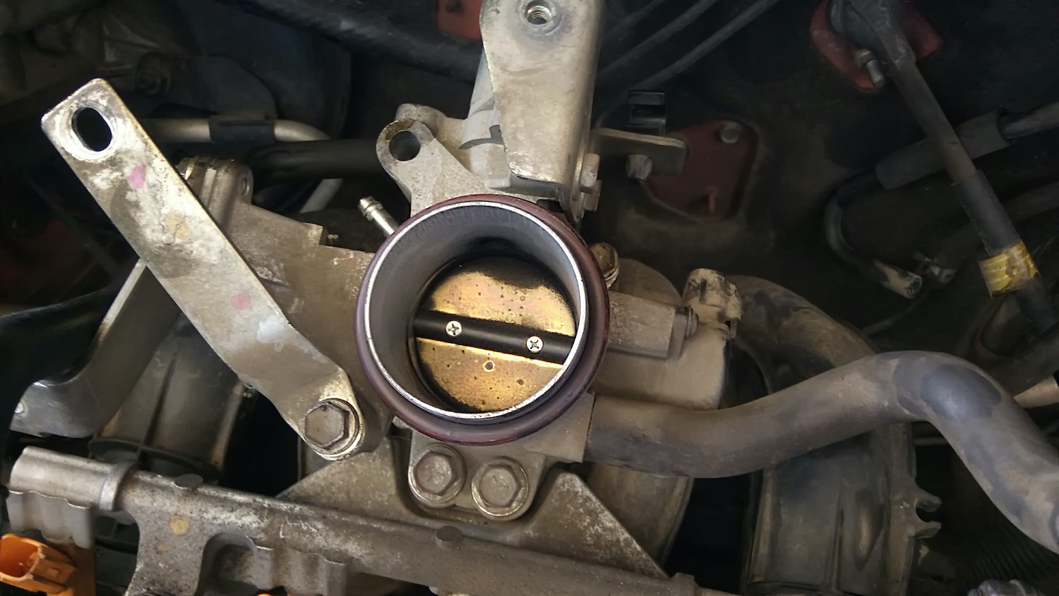
1. Faulty TPS sensor (most common cause)
The throttle position sensor functions as a potentiometer with a resistive track. As the throttle shaft rotates, a wiper slides along the track, changing resistance and thus output voltage.
Failure mechanism:
Over time, the resistive track wears out, creating “dead zones”—areas with high resistance or complete opens. When the wiper passes over such a zone, resistance spikes, and voltage at the signal terminal drops below 0.2 V.
Additional factors:
- Moisture intrusion due to a non-sealed sensor housing.
- Overheating (sensor located on a hot engine).
- Wear from vibration and frequent accelerator use.
2. Open or short in the wiring
Signal wire open:
The path from TPS to ECM is interrupted. The control module sees no signal (0 V or near zero voltage).
Signal wire short to ground:
The signal terminal contacts the vehicle ground. Voltage at the ECM input drops to zero, triggering P0122.
5 V reference wire open:
The sensor loses power and cannot produce a proper signal.
Typical damage locations:
- Bends near connectors (wire breaks inside insulation).
- Wiring harness routed near hot engine parts (insulation melts).
- Rubbing against sharp metal edges (insulation wears through, exposed wire shorts to ground).
3. Corrosion and poor connector contact
Mechanism:
Moisture (condensation, washing water) enters the TPS connector, oxidizing copper contacts. The oxide layer adds resistance, lowering signal voltage.
Signs:
Greenish deposits on connector pins, black discoloration, loose contacts. Wires may appear intact, but the sensor registers a low signal due to high contact resistance.
4. Low 5 V reference voltage
The ECM supplies a 5 V reference to the TPS. If there is a short circuit in this line (for example, another sensor on the same line shorts), the reference voltage drops to 3–4 V.
Effect on TPS:
The sensor acts as a voltage divider. With a 3 V reference instead of 5 V, the output signal proportionally decreases. A closed throttle may output 0.15 V instead of 0.5 V, causing the ECM to register P0122.
Check:
Measure voltage between the reference terminal (Vc) and ground (E2) with the ignition on. Normal: 4.8–5.2 V. Below 4.5 V indicates a problem in the ECM reference line or, less commonly, the control module itself.
5. Mechanical throttle issues (less common)
Carbon deposits on the throttle body:
Build-up can prevent proper throttle movement. The sensor reads actual position, but the ECM may see values it does not expect.
Throttle shaft sticking:
Bearing wear or deformation can affect throttle return and TPS readings.
6. ECM malfunction (rare cause)
Defect in the control module input stage. If the circuit responsible for reading the TPS signal is damaged (for example, by a voltage spike), the ECM may read a low signal even with intact wiring and sensor.
Diagnosis:
Only after excluding all other causes. Testing involves replacing the ECM with a known-good unit or using specialized equipment to check input parameters.
How to diagnose P0122 yourself: step-by-step guide
Disclaimer:
This information is general and does not replace professional consultation. When working with vehicle electrical circuits, observe safety precautions: turn off the ignition when connecting/disconnecting connectors, and avoid shorting pins with tools.
Diagnosis goal:
Locate the component causing the low TPS signal. You will need:
- OBD-II scanner with live data capability.
- Digital multimeter (DC voltage and resistance modes).
- Back-probing pins or needle probes (to test connectors without disconnecting them).
- Contact cleaner spray.
- Dielectric grease for connector protection.
Step 1: Read error codes and freeze frame data
Connect the OBD-II scanner and read all stored codes. Record freeze-frame data—a snapshot of conditions when P0122 occurred:
- TPS voltage (V).
- TPS relative position (%).
- APP (accelerator pedal position, %) on vehicles with electronic throttle.
- Engine RPM, MAP (manifold absolute pressure).
Why this matters:
Freeze-frame data shows the conditions when the code was stored: idle, acceleration, or cruising. This narrows down the search area.
Step 2: Visual inspection of connector and wiring
Turn off the ignition. Disconnect the TPS connector (usually mounted on the throttle body). Inspect:
- Connector pins: check for green oxidation, black discoloration, or moisture.
- Connector housing: cracks, broken locks.
- Wires near the connector: insulation cracks, bends, melting signs.
If corrosion is found:
- Clean contacts with contact cleaner spray and let dry.
- Apply dielectric grease inside the connector to protect against moisture.
Step 3: Check 5 V reference voltage
Turn the ignition on (do not start the engine). Connect the multimeter:
- Red probe to reference terminal (Vc/REF).
- Black probe to ground terminal (E2/GND) or battery negative terminal.
Normal: 4.8–5.2 V.
If below 4.5 V:
- Issue in the ECM reference voltage line.
- Check for other sensors on the same 5 V line (MAP, and on some vehicles other 5 V sensors) that may be shorting it.
- Disconnect sensors one by one while monitoring voltage.
Step 3a: Check APP↔TPS correlation (for vehicles with electronic throttle control, ETC)
In vehicles with ETC, where the accelerator pedal is not mechanically linked to the throttle, the ECM compares signals from two independent sensors: APP (pedal) and TPS (throttle).
How to check:
Open live data on the scanner. Press the accelerator pedal. Observe:
- APP increases (pedal pressed), but TPS remains low (0–2%)—mismatch. Problem in TPS circuit or sensor.
- APP and TPS increase synchronously—TPS is good; issue may be mechanical or related to ECM calibration.
| APP (%) | TPS (%) | Interpretation | Action |
|---|---|---|---|
| 0 | 0–2 | Normal (pedal released) | – |
| 50 | 0–2 | Mismatch: TPS unresponsive | Check TPS wiring, 5 V reference, sensor |
| 50 | 48–52 | Match (ETC functioning) | Problem elsewhere (adaptation, mechanics) |
Step 4: Measure TPS signal voltage
Turn the ignition on. Connect the multimeter (or use back-probing needles without disconnecting the sensor):
- Red probe to signal terminal (S).
- Black probe to ground (E2) or battery negative terminal.
Check voltage:
- Closed throttle: should be 0.4–0.7 V (varies by vehicle).
- Fully open throttle (WOT): 4.2–4.7 V.
Press the accelerator smoothly and watch voltage. It should rise steadily without dropouts or spikes.
Signs of fault:
- Voltage constantly below 0.2 V at closed throttle—sensor faulty or signal wire shorted to ground.
- Drops or spikes (for example, 0.5 V → 0.1 V → 1.0 V)—worn resistive track, dead zones.
Step 5: Check wiring for opens and shorts
Disconnect TPS and ECM connectors (if accessible). Test wiring with a multimeter:
Signal wire continuity:
Connect probes between the TPS signal terminal and the corresponding ECM terminal. Resistance should be under 1 ohm (wire intact).
Insulation check (no short to ground):
Connect one probe to the signal wire, the other to vehicle ground. Resistance should be over 10 MΩ (no short). If resistance is low (under 1 kΩ), the wire is shorted to ground.
Step 6: Check ground quality (voltage drop on ground circuit)
Turn the ignition on. Connect the multimeter:
- Red probe to E2 terminal on the TPS connector.
- Black probe to battery negative terminal.
Normal: voltage drop close to 0 V (usually under 0.1 V).
If above 0.1 V:
Poor ground quality. Check the engine ground point to the chassis (oxidation, loose bolt). Clean and tighten.
Step 7: Assess throttle mechanics
Remove the air duct and visually inspect the throttle body:
- Carbon deposits: black buildup on throttle edges. Clean with throttle body cleaner and a soft brush.
- Sticking: manually (ignition off) rotate the throttle shaft. It should move freely without binding. If sticking occurs, possible shaft wear or throttle body deformation.
After cleaning, vehicles with ETC may require an idle relearn. The procedure depends on the make and model (see the manufacturer service manual). A battery disconnect does not reliably perform this procedure on all vehicles; a scan tool procedure may be required.
Alternative method: TPS resistance/oscilloscope check (for potentiometric sensors)
For cable-operated TPS (potentiometer):
Remove the sensor. Set the multimeter to resistance mode between the Vc and E2 terminals. Manually rotate the sensor shaft. Resistance should change smoothly without dropouts.
For Hall effect sensors (contactless):
Check only with an oscilloscope or scanner (voltage). Resistance measurement is not useful.
Ways to fix P0122 fault
After diagnosis, proceed to repair. The sequence depends on the identified cause.
1. Clean and restore connector, repair wiring
If corrosion is found on the connector:
- Clean contacts with electrical contact cleaner. Use an appropriate terminal-cleaning tool if needed.
- Let dry, then apply dielectric grease inside the connector.
If an open wire is found:
- Strip wire ends, remove 0.20–0.28 in. (5–7 mm) of insulation.
- Repair the connection using an OEM-approved wiring repair method.
- Restore insulation with heat-shrink tubing or quality electrical tape.
If a wire is shorted to ground:
- Locate the damage (usually worn insulation in the harness).
- Cut out the damaged section and replace it with the same gauge wire.
- Repair the joints and restore insulation.
After repair:
Check 5 V reference and TPS signal voltage. If values are normal (0.4–0.7 V at closed throttle), clear the code and perform a test drive.
2. Replace throttle position sensor (TPS)
When to replace:
If the sensor is faulty (resistance out of range, voltage does not increase smoothly, signal drops).
Parts selection:
- Original sensor: warranty and service life vary by make and model; verify by VIN or parts catalog.
- Quality aftermarket (Bosch, Delphi, Denso): quality and warranty vary by brand and application.
- No-name budget parts: not recommended—higher risk of early failure or repeat codes.
Replacement procedure:
- Purchase a sensor compatible with your model (verify by VIN).
- Remove the old sensor (usually secured by two screws on the throttle body).
- Install the new sensor aligned with any index marks. If none are present, refer to the service manual.
- Tighten screws (do not overtighten to avoid damage).
- Reconnect the connector.
Post-installation check:
Turn the ignition on and measure voltage:
- Closed throttle: 0.4–0.7 V.
- Open throttle: 4.2–4.7 V.
ETC adaptation:
Vehicles with electronic throttle may require relearn (calibration). Procedure depends on the manufacturer:
- Some vehicles may allow a key-on/key-off relearn, but procedures vary by model.
- Specific procedures: see the manufacturer service manual or perform adaptation via scanner (“TPS Adaptation” or “Throttle Body Calibration”).
Brand-specific notes (examples of nuances)
Peugeot 308/3008/408 (ETC, shared 5 V line)
Feature: TPS is integrated into the throttle body and may not be sold separately. If TPS fails, the entire throttle body may need to be replaced.
Adaptation: may require a Peugeot/Citroën-compatible diagnostic scanner (Lexia, Diagbox), depending on the model.
5 V line nuance: MAP, TPS, and sometimes intake air temperature sensors may share the 5 V line. If P0122 occurs with MAP codes, check the 5 V line for shorts.
GM 3.8L (cable throttle)
TPS installation tip (from forum user):
“The tab inside the sensor must contact the rotating pins in the throttle body. For GM 3.8L engines, insert the sensor with the connector at 12 o’clock (like on a clock face), then rotate to 9 o’clock for final position.”
Important: this is not a universal rule. Refer to your model’s service manual. Incorrect sensor orientation can cause a low signal.
3. ECM check and repair
When to suspect ECM:
Only after excluding all other causes (wiring intact, TPS good, 5 V reference normal, but ECM input signal still low).
Actions:
- Check other sensors powered by the same 5 V line (MAP and other 5 V sensors, depending on the vehicle). If they also fail, the problem may be in the ECM.
- Check ECM fuses and relays.
- If the reference line is good but the signal reads low, an input stage defect in the ECM is possible.
ECM repair/replacement:
Requires specialized service. A DIY option is to replace the ECM with a known-good unit (used or new). Programming (VIN coding, immobilizer adaptation) is typically required after replacement.
Clear fault code and verify repair
After fixing the issue:
- Connect an OBD-II scanner and clear stored codes (“Clear Codes” function).
- Turn off the ignition and disconnect the scanner.
- Perform a drive cycle:
- Idle for 2 minutes.
- Accelerate to 37 mph (60 km/h) → brake → repeat 2–3 times.
- Drive at 50–62 mph (80–100 km/h) for 5 minutes.
- Read codes again. Ensure P0122 does not return.
- Check TPS% and TPS voltage in live data: values should smoothly vary through the expected operating range without dropouts.
Post-repair checklist for P0122
- 5 V reference voltage: 4.8–5.2 V (multimeter, ignition ON).
- TPS signal voltage: 0.4–0.7 V (closed), 4.2–4.7 V (WOT).
- Ground voltage drop (E2): <0.1 V.
- TPS% on the scanner rises smoothly through its range without jumps.
- APP% (ETC) reasonably tracks TPS%.
- P0122 does not return after a 6–12 mile (10–20 km) drive cycle.
Is it safe to drive with P0122 and what are the consequences?
Driving with P0122 is strongly discouraged. Here’s why:
Driving safety
The ECM may enter limp mode, limiting power. During overtaking or other maneuvers, the vehicle may not respond normally to the accelerator pedal, creating a safety risk.
Engine consequences
Incorrect TPS signal can cause fuel-air mixture calculation errors:
- Lean mixture: can contribute to spark knock, higher combustion temperatures, and possible engine damage.
- Rich mixture: incomplete combustion, carbon buildup, spark plug fouling.
Fuel consumption
The ECM cannot properly meter fuel. Fuel consumption may increase, depending on vehicle condition and calibration.
Catalytic converter
An incorrect mixture can affect exhaust composition. In some cases, prolonged operation may overheat or damage the catalytic converter.
Idle and stability
Engine stalls at traffic lights, RPM fluctuates. This causes drivability issues and can increase wear on ignition components (spark plugs, coils).
Conclusion: fix the fault promptly. Diagnosing and repairing wiring or replacing the sensor is usually far less expensive than major engine or catalytic converter repairs.
How P0122 appears on diagnostic scanners
When connecting an OBD-II scanner, you will see:
- DTC P0122 stored or pending.
- Freeze frame—a snapshot of parameters when the code set: TPS voltage, TPS relative (%), APP (%), RPM, MAP, coolant temperature.
Live data interpretation
Pay attention to these parameters (PIDs):
| Parameter (PID) | Normal range | P0122 indication |
|---|---|---|
| TPS voltage (V) | 0.5–0.7 V (closed), 4.2–4.7 V (open) | <0.2 V constantly or signal drops |
| TPS relative (%) | Varies by vehicle through the normal throttle range | 0–2% when pedal pressed |
| APP (%) | Matches pedal position | Increases but TPS does not change |
| 5 V reference (V) | 4.8–5.2 V | <4.5 V |
| Ground voltage drop (V) | <0.1 V | >0.1 V |
TPS voltage (V):
Abnormally low value, for example, 0.1–0.3 V at closed throttle (normal 0.5–0.7 V).
TPS relative (%):
Shows 0–2% even when the accelerator is pressed, meaning the ECM reads a low signal and interprets it as “throttle closed.”
APP (accelerator pedal position, %):
On ETC vehicles with P0122, APP increases (pedal pressed) but TPS remains low—mismatch. The ECM logs the discrepancy and stores the code.
5 V reference voltage:
Reference voltage supplied by ECM to sensors. Below 4.5 V indicates a problem in the ECM reference line (short in another sensor circuit, control module defect).
Related codes
Possible codes related to the TPS and throttle control system:
| Code | Meaning | Key difference from P0122 |
|---|---|---|
| P0120 | TPS “A” circuit malfunction | General circuit fault, does not specify low or high |
| P0121 | TPS range/performance mismatch | Signal out of expected range (not necessarily low) |
| P0123 | High TPS “A” input signal | Voltage above normal (>4.7 V), opposite of P0122 |
| P0124 | Intermittent TPS signal | Unstable signal (spikes, drops), not constantly low |
| P0222 | Low TPS “B” input signal | Same as P0122 but for second sensor channel (dual TPS systems) |
| P0223 | High TPS “B” input signal | High signal on second channel |
| P2101 | Throttle actuator control system malfunction | Problem with throttle motor (ETC) or its control |
If P0122 and P0222 occur simultaneously, the issue may be with the shared 5 V reference line or ground.
Repair costs and parts selection
Note: the figures below are general estimates. Check local prices in your area, as labor rates and parts costs vary by location, vehicle model, and parts availability.
Diagnostics
Cost: varies by region and technician.
Includes: code scanning, freeze-frame reading, wiring inspection, voltage measurements, TPS testing.
TPS replacement
Labor cost: depends on sensor accessibility (some models require removing air ducts or covers).
TPS sensor cost:
| Part type | Warranty | Lifespan | Failure risk | Recommendation |
|---|---|---|---|---|
| Original | Varies | Varies | Low | Best choice for long-term use |
| Premium aftermarket | Varies | Varies | Medium | Bosch, Delphi, Denso – reliable alternatives |
| No-name | Varies | Varies | High | Not recommended – code may recur |
Selection tips:
- Avoid cheap unbranded parts. Potentiometers in such sensors are often low quality, causing repeat faults.
- Verify compatibility by VIN or parts catalog.
- Check warranty and return policy with the seller.
- If possible, buy OE-quality or genuine parts for longer service life.
Electronic throttle control (ETC) adaptation
Cost: depends on vehicle model and required equipment (manufacturer-compatible diagnostic scanner).
When needed: after TPS replacement, throttle body cleaning, or throttle body replacement on ETC vehicles.
Additional expenses
Costs for wiring repairs, cleaning, and adaptation vary widely by vehicle and shop labor rates—confirm locally before purchasing parts.
- Wiring repair: cost of wire, solder, heat-shrink tubing—usually minor.
- Throttle body cleaning: cost of throttle body cleaner.
Prevention: how to avoid P0122 recurrence
To prevent P0122 from returning:
- Regularly clean the throttle body.
Carbon deposits reduce engine response and can contribute to TPS-related problems. Recommended interval depends on operating conditions (fuel quality, air filter condition). Guideline: as needed or when symptoms appear (unstable idle, sluggish response). - Inspect TPS connector during maintenance.
Visually check for moisture and oxidation. If corrosion is present, clean and apply dielectric grease. - Secure wiring harnesses.
TPS wires should not sag or rub against moving engine parts. Use clips or ties to secure the harness. - Protect connectors from moisture.
Avoid aggressive high-pressure washing under the hood. Water jets can penetrate the TPS connector and cause corrosion. - Use quality parts.
Cheap sensor alternatives often fail sooner. Saving on the sensor can lead to repeat repairs.
Brand and throttle type specifics
Electronic throttle control (ETC / drive-by-wire)
On vehicles with ETC (no mechanical cable between pedal and throttle), P0122 diagnosis has nuances:
APP and TPS correlation:
The ECM compares accelerator pedal (APP) and throttle position (TPS) signals. If the discrepancy exceeds allowed limits (manufacturer-dependent) or TPS is constantly low, P0122 is logged.
Adaptation is critical:
After throttle cleaning or TPS replacement, adaptation may be required. Without it, the ECM may use old calibration data and the code may return.
General adaptation procedure:
- Some vehicles may respond to a battery disconnect or key cycle.
- Or perform adaptation via scanner (procedure varies by make; see service manual).
Example procedure (some Toyota models):
- Turn ignition on (do not start engine).
- Wait 10 seconds.
- Turn ignition off.
- Repeat 2–3 times.
Cable-operated throttle
On older vehicles with cable throttle:
- No APP signal—diagnosis is limited to TPS and wiring.
- Throttle cable or stop adjustment may affect readings: if the cable is too tight or misadjusted, throttle angle may not return as expected.
- Adaptation is usually not required (except idle relearn on some models).
Shared 5 V line
Some vehicles supply 5 V reference to multiple sensors (MAP, TPS, and sometimes other sensors). Important: the MAF sensor is typically not part of the 5 V reference circuit—do not confuse the two.
How to localize the problem:
If a short occurs in one sensor circuit, the 5 V reference drops for all. Check related circuits by disconnecting sensors one by one and monitoring 5 V line voltage.
Typical sensors on 5 V line (model-dependent):
- MAP (manifold absolute pressure sensor).
- TPS (throttle position sensor).
- Other 5 V sensors depending on the vehicle.
| Throttle type | Diagnostic feature | Repair nuance |
|---|---|---|
| ETC (electronic) | Check APP/TPS correlation, adaptation after repair | Adaptation may require a scanner or manufacturer procedure |
| Cable-operated | Only TPS, check cable adjustment | Adjust throttle stop, idle relearn (if applicable) |
| Shared 5 V line | Check all sensors on this line | Isolate faulty sensor, restore reference voltage |
Conclusion
DTC P0122 indicates an electrical fault in the throttle position sensor circuit, which can affect safety and drivability. The ECM detects a low signal (below 0.17–0.2 V) instead of the expected 0.5–4.5 V range, may enter limp mode, and can limit power.
Diagnosis: OBD-II scanner plus multimeter. Check 5 V reference voltage, TPS signal voltage (smoothness, no dropouts), wiring and connector condition, and ground quality. Do not rule out mechanical throttle issues.
Repair: wiring/connector repair (cleaning, proper wiring repair, insulation restoration), TPS replacement with an OE or quality aftermarket sensor, ETC adaptation if required, and verification with a test drive.
Consequences of driving with P0122: loss of power control, increased fuel consumption, engine drivability issues due to incorrect mixture, and possible catalytic converter damage. Repair should not be delayed.
Checklist: 5 steps to resolve P0122
- Read codes and freeze frame (OBD-II scanner).
- Check 5 V reference and ground (multimeter, ignition ON).
- Measure TPS signal voltage (0.4–0.7 V closed, 4.2–4.7 V WOT).
- Fix the defect (wiring/sensor).
- Clear the code, test drive, verify (6–12 miles (10–20 km), check live data).
Disclaimer:
This article is for educational purposes and does not replace professional vehicle inspection. Voltage values and diagnostic procedures may vary by model—refer to the manufacturer’s service manual. If P0122 occurs, consult a qualified technician for diagnosis and repair.
Frequently asked questions
Is it possible to drive with P0122?
It is strongly discouraged. There are safety risks during overtaking or merging because the vehicle may not accelerate normally. Limp mode limits power, fuel consumption may increase, and prolonged operation can cause drivability issues or catalytic converter damage.
On which cars is the P0122 error most common?
P0122 can occur on many makes and models. It is common on vehicles with either cable-operated or electronic throttle systems because the code is tied to TPS circuit faults, wiring problems, or low 5 V reference voltage. Failure patterns vary by vehicle, and broad public statistics are limited.
How much does it cost to replace the TPS?
Costs vary by vehicle, part quality, and local labor rates. Labor depends on sensor accessibility. The price of the part also varies widely between genuine and aftermarket options. On electronic throttle systems, you may also need a relearn or adaptation procedure after replacement.
Does a faulty TPS affect engine start?
Yes, hard starting and stalling are possible on some vehicles. The ECM uses throttle position input as part of its fuel calculation during startup. A low or erratic signal can contribute to unstable starting or immediate stalling after startup.