P0141 – oxygen sensor heater circuit malfunction Bank 1 Sensor 2 (post-catalyst). Four main causes: faulty sensor heater, damaged wiring or connector, blown fuse, and less commonly, PCM/ECM failure. Basic check: diagnostic scanner → fuse → +12 V power and ground at connector → heater resistance (manufacturer’s manual specification, typically 2–20 ohms).
Information is general and does not replace professional consultation. Observe safety precautions when working with electrical equipment and lifting the vehicle.
Page contents
Conditions for DTC P0141 activation (enable criteria)
The powertrain or engine control module (PCM/ECM) registers code P0141 based on monitoring the heater circuit of oxygen sensor Bank 1 Sensor 2. The following conditions are required for the diagnostic to trigger:
- Coolant temperature: above threshold (usually 158–176°F (70–80°C)) – the PCM/ECM verifies that the engine is sufficiently warmed up for proper sensor operation.
- On-board voltage: stable (typically 11–15 V) – ensures the heater receives nominal power.
- Time since engine start: usually a few seconds – the PCM/ECM waits for the heater to reach operating current.
- Two-trip logic: the code is typically stored after detecting the fault in two consecutive drive cycles.
Note: specific threshold values vary by make and model. The PCM/ECM measures current through the heater (usually by switching ground). If the current is outside set limits—absent, too low, or excessively high—the system records a fault. Detection algorithms differ among manufacturers. Always consult your vehicle’s service manual.
Error P0141: meaning of the DTC, causes, and troubleshooting methods
Error P0141 is a diagnostic trouble code (DTC) indicating a problem in the heater circuit of oxygen sensor Bank 1 Sensor 2. This sensor is located after the catalytic converter and monitors catalyst efficiency. When the PCM/ECM detects P0141, it means the sensor’s heating element does not reach operating temperature within the specified time, or the heater circuit is not operating as expected. The heater circuit may have an open circuit, short circuit, or parameter deviation.
The heater helps the oxygen sensor reach its operating temperature (typically 1,112–1,472°F (600–800°C)) faster, which is necessary for accurate measurement of oxygen concentration in exhaust gases. If the circuit is faulty, the PCM/ECM may extend open loop operation during warm-up. This temporary mode disables oxygen sensor feedback for mixture correction, affecting fuel delivery and increasing emissions.
The code appears at engine start when the PCM/ECM checks current through the heating element. If current is absent or outside allowable limits (specific values depend on vehicle model; refer to the manufacturer’s manual), the system logs the fault and stores Freeze Frame data—engine conditions at the time the fault occurred: RPM, temperature, and load.
“P0141 concerns the post-catalyst sensor heater; most often the cause is the sensor itself or wiring,” note ASE-certified technicians.
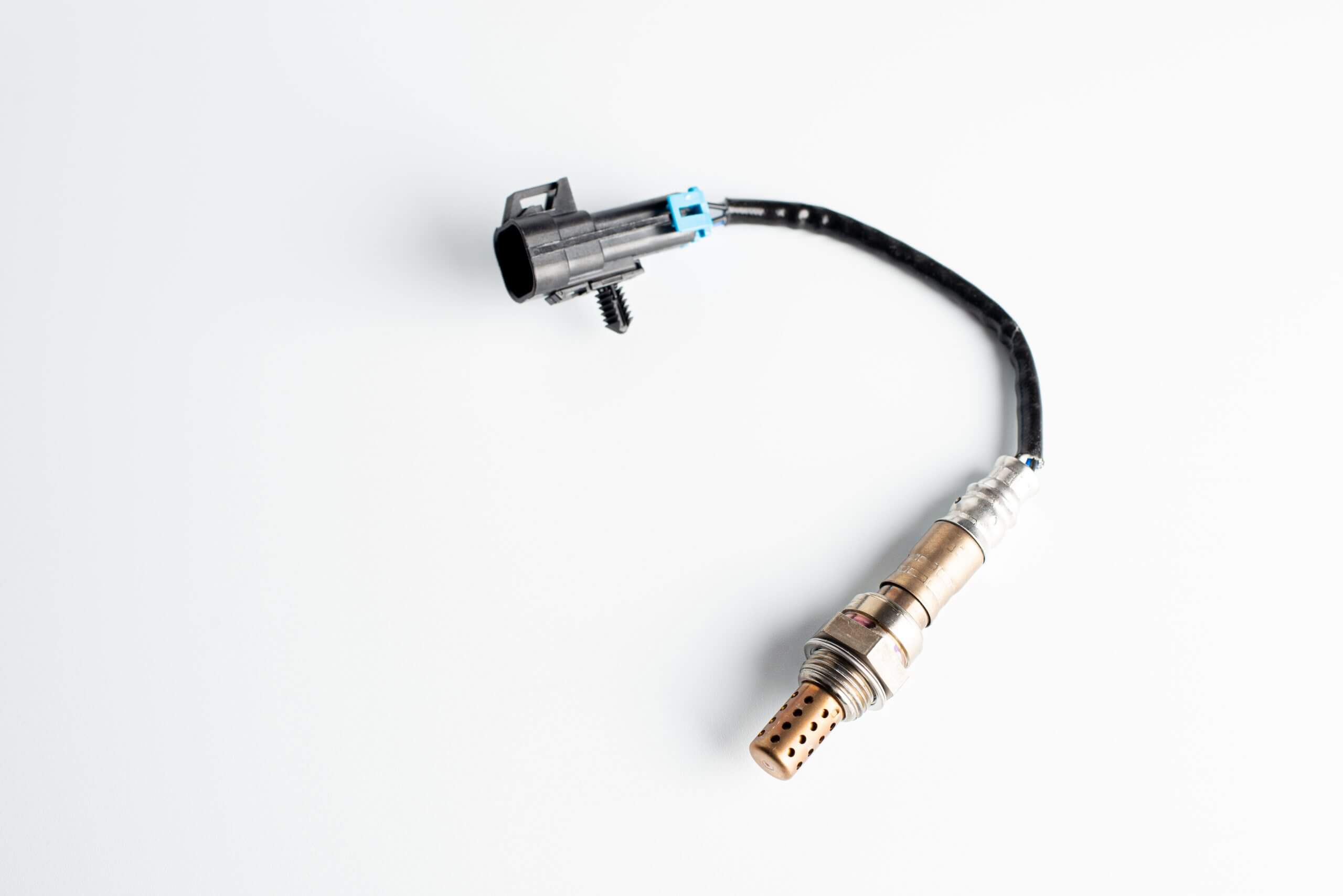
Location and function of the second oxygen sensor (B1S2)
The second oxygen sensor (O2 sensor) Bank 1 Sensor 2 is located in the exhaust system after the catalytic converter on Bank 1. Inline engines (I4) have only one cylinder bank—Bank 1—and B1S2 is installed after the single catalyst. In V-type engines (V6, V8), Bank 1 refers to the side with cylinder #1 (usually driver or passenger side depending on design), and B1S2 is positioned after that bank’s catalyst.
B1S2 performs a key function: it assesses catalytic converter efficiency. It measures oxygen concentration in exhaust gases after the catalyst and sends data to the PCM/ECM. The PCM/ECM compares readings from the upstream sensor (B1S1) and downstream sensor (B1S2). If the catalyst functions properly, the B1S2 signal is relatively stable and low—indicating low oxygen as the catalyst reduces pollutants. If the catalyst degrades, the B1S2 signal may fluctuate similarly to B1S1, and the PCM/ECM may set code P0420 (catalyst efficiency below threshold).
The B1S2 heater ensures the sensor quickly reaches operating temperature (usually 1,112–1,472°F (600–800°C)) after engine start. Without the heater, the sensor would warm only from exhaust gases, taking several minutes. During this time, the PCM/ECM lacks catalyst data and may not complete OBD-II monitor tests.
Operation flow: engine → exhaust manifold → B1S1 sensor (pre-catalyst) → catalytic converter → B1S2 sensor (post-catalyst) → exhaust pipe.
Difference between A/F (air/fuel) and O2 sensors: on some modern vehicles, the upstream sensor B1S1 may be a wideband A/F sensor, which measures the air-fuel ratio more precisely for mixture control. The downstream sensor B1S2 usually remains a narrowband O2 sensor for catalyst monitoring. This does not affect P0141 diagnosis—the code relates only to the B1S2 heater circuit.
Main symptoms and signs of code P0141
When the PCM/ECM registers P0141, the first noticeable sign for the driver is the illumination of the check engine light. This is the primary symptom but not the only one.
In most cases, the vehicle continues to operate without obvious issues, but indirect signs may appear:
- Check engine light on, P0141 code active
- Possible increase in fuel consumption (the PCM/ECM remains longer in open loop during warm-up due to sensor unavailability)
- Slightly rough cold-start operation—mild vibrations or fluctuating idle speed
- Rarely: slight hesitation during acceleration if the fuel injection system compensates for missing sensor data
The key distinction of P0141 from other codes is that symptoms are usually mild. The B1S2 sensor does not directly control fuel correction (this is done by the upstream sensor), but its missing data can block OBD-II monitor readiness and cause an emissions test failure. Prolonged neglect may lead to elevated exhaust emissions and delayed detection of catalyst problems.
Prompt diagnostic scanning to retrieve Freeze Frame and related codes is recommended. This helps identify fault conditions and rule out multiple issues.
Main causes of error P0141
Error P0141 arises from one of four primary causes. Each has its frequency and characteristic signs.
Faulty oxygen sensor heater element
Most often, the error is caused by failure of the heater in the Bank 1 Sensor 2 oxygen sensor. Inside the sensor is a resistive heating element that heats the sensing part to operating temperature (usually 1,112–1,472°F (600–800°C)). Over time, the element can fail—resulting in an open circuit or short circuit—and the PCM/ECM logs the code.
The typical resistance of a functional heater when cold depends on sensor manufacturer and vehicle model (check the manual or sensor catalog). An open circuit shows infinite resistance on a multimeter; a short circuit shows near zero. Since this sensor is post-catalyst, its malfunction affects catalyst efficiency monitoring and OBD-II readiness for emissions testing.
Damaged wiring or sensor connector
Wiring and the connector to the sensor are located under the vehicle, exposed to moisture, dirt, road chemicals, and high temperatures from the exhaust system. This leads to common issues:
- Wire breaks from abrasion against the body or exhaust pipe
- Short to ground due to damaged insulation
- Corrosion of connector terminals—often green corrosion on the pins
- Melted insulation from proximity to hot exhaust components
Any damage in the heater circuit (power +12 V or ground) prevents the PCM/ECM from monitoring current through the heater and triggers P0141. Visual inspection of the wiring harness and connector often reveals the cause without costly sensor replacement.
Blown fuse or faulty heater relay
The oxygen sensor heater circuit is usually protected by a fuse in the underhood fuse box and sometimes controlled by a relay or transistor switch inside the PCM/ECM. If the fuse is blown, the heater receives no power, and the sensor fails to reach operating temperature.
Checking is straightforward: locate the fuse according to the vehicle’s fuse diagram (often labeled O2 Heater, EFI, or similar), visually inspect it, and replace it with the same rating fuse. It is important to identify the cause of fuse failure. Repeated fuse blowing may indicate a short circuit in the wiring or a faulty sensor.
PCM/ECM malfunction
A rare but possible cause is failure of the heater control channel within the PCM/ECM itself. For example, the transistor switching ground for the heater element may fail. This cause should be confirmed only after systematically ruling out sensor, wiring, fuse, and relay issues.
PCM/ECM diagnostics require professional equipment and knowledge of the specific vehicle’s wiring. At home, you can only check for a control signal at the sensor connector with the ignition on. If voltage is present, wiring is intact, the sensor is new, and the error persists, PCM/ECM malfunction is possible.
| Cause | Symptom/Test | Quick action |
|---|---|---|
| Faulty sensor heater | Resistance ∞ ohms or ~0 ohms (check manual) | Replace O2 Bank 1 Sensor 2 |
| Damaged wiring/connector | Visual: abrasion, melting, corrosion; continuity test for open/short | Repair wiring section, clean connector terminals |
| Blown fuse/relay | Visual fuse inspection in fuse box | Replace fuse, locate short circuit |
| PCM/ECM fault | Power and ground present at sensor connector with good sensor/wiring | PCM/ECM diagnostics at a specialized repair facility |
Step-by-step diagnosis to accurately identify cause of P0141
A correct sequence of actions helps find the real cause and avoid unnecessary parts replacement. Diagnosis proceeds from simple to complex.
Step 1: OBD-II scanner diagnosis
Connect a diagnostic scanner to the vehicle’s OBD-II port (usually under the steering column). Read stored fault codes and record Freeze Frame data—a snapshot of engine conditions at the time the fault occurred: RPM, coolant temperature, load, and speed. Check for related codes: P0135 (heater B1S1 pre-catalyst), P0161 (heater B2S2), P0420 (catalyst efficiency). If P0141 appears with P0420, first fix the sensor heater issue as it may distort catalyst data.
Monitor live data: voltage signal from the B1S2 sensor and monitor readiness status (catalyst monitor, oxygen sensor monitor). If the monitor is not ready, it supports the possibility that the sensor is not reaching operating temperature.
Step 2: Visual inspection of wiring and connector
Raise the vehicle on a lift or place it over an inspection pit. Inspect the wiring harness leading to the B1S2 sensor under the vehicle. Look for:
- Abraded sections (contact with body or exhaust pipe)
- Melted insulation (close to hot components)
- Corrosion on connector—typical green deposits on contacts
- Secure sensor harness routing and attachment to the body/chassis
If damage is found, repair the wiring using solder and heat-shrink tubing, clean connector terminals, and apply dielectric grease.
Step 3: Check heater circuit fuse
Locate the heater fuse in the vehicle’s service documentation or fuse box cover (often labeled O2 Heater, EFI, or Sensor Heater). Remove the fuse and visually inspect the element. If blown, replace it with the same rating fuse and start the engine. Repeated fuse failure indicates a short circuit—return to wiring and sensor inspection.
Step 4: Measure heater resistance with a multimeter
Disconnect the B1S2 oxygen sensor connector. Identify the heater circuit pins—usually two separate wires (often white or gray), distinct from the oxygen signal wires. Set the multimeter to resistance (ohms) and measure between the heater pins.
Compare the reading with the sensor manual or catalog for your vehicle model. Infinite resistance indicates an open coil; near zero indicates a short. In both cases, sensor replacement is required.
Step 5: Check voltage at sensor connector
With the ignition on (engine off), verify +12 V power on one heater pin and a good ground on the other, as applicable for the vehicle’s wiring. If power is absent, the problem lies in the wiring from the fuse box to the sensor, relay, or PCM/ECM. If power and ground are present but the code persists after sensor replacement, the PCM/ECM control circuit may be faulty.
To confirm, connect a 12 V bulb (5–10 W) in place of the sensor heater—it should illuminate, indicating circuit presence. If the bulb does not light, the fault is in the power supply circuit.
How to fix error P0141: repair methods
Information is general and does not replace professional consultation. Work on exhaust and electrical systems requires safety precautions—risk of burns and short circuits.
To fix and permanently eliminate P0141, follow diagnostic results strictly. Each cause requires a specific repair approach.
If the oxygen sensor heater is faulty (B1S2)
If resistance measurement shows an open or short circuit in the heater, replace the sensor. Disconnect the connector, unscrew the sensor with a wrench (usually 7/8 in. (22 mm))—use penetrating oil if the sensor is seized in the exhaust pipe threads. Screw in the new sensor by hand until seated, then tighten with a wrench. If the vehicle manufacturer recommends it, apply anti-seize compound to the threads to prevent sticking (check the manual—some sensors come pre-coated). Reconnect the connector and ensure a secure fit. Choose a quality aftermarket brand (Bosch, Denso, NGK) or OEM part—verify compatibility by length, connector type, and wire count.
If wiring is damaged
If a break or short is found in the harness, repair the section by soldering. Do not use electrical tape alone—it does not withstand heat and moisture under the vehicle. Strip wires, solder the break, insulate with heat-shrink tubing, and protect with corrugated loom. If the connector is corroded, clean the terminals with contact cleaner, dry them, and apply dielectric grease. Check secure harness mounting to the body/chassis—wires must not contact the exhaust system.
If fuse is blown
Replace the fuse with one of the same rating. Before installation, visually inspect the wiring for short circuits—if insulation is melted, fix this first. Repeated fuse blowing likely indicates a short in the sensor or wiring.
After all repairs—clear the code and verify
Connect an OBD-II scanner and clear code P0141. Start the engine, allow it to reach operating temperature (5–10 minutes), then perform a test drive (typical monitor readiness drive cycle; the specific cycle depends on the manufacturer—check the manual). This allows the PCM/ECM to complete monitor tests and confirm the code does not return. Verify monitor readiness—if all are ready, the repair was successful.
If P0141 reappears, repeat heater circuit diagnosis and check the PCM/ECM.
Does LPG installation affect the occurrence of error P0141?
LPG systems rarely directly cause P0141, as the code relates specifically to the sensor heater circuit, not the sensor signal or fuel system operation. However, there are indirect scenarios where LPG equipment may affect diagnostics.
First, running on gas changes exhaust gas temperature—typically, gas combustion temperature differs from gasoline operation. This may affect B1S2 sensor operating conditions but not the heater itself.
Second, incorrect PCM/ECM tuning for LPG or a non-standard O2 sensor emulator can mask or complicate code diagnosis. The emulator substitutes the oxygen sensor signal but should not affect the heater circuit. If improperly installed or defective, it may introduce electrical interference.
Third, LPG installation often involves wiring modifications under the hood and under the vehicle. Damage to the O2 sensor wiring harness or grounds during installation can cause P0141.
Mini checklist for LPG vehicle owners:
- Test on gasoline: temporarily disable LPG and drive on gasoline. Monitor live data to see if P0141 persists.
- Disable emulator: if an O2 sensor emulator is installed, disconnect it for a clean test and check if the code appears without it.
- Check power and ground: perform steps 4–5 of diagnosis (heater resistance, +12 V power/ground).
- Check LPG and chassis grounds: ensure the LPG installation did not disrupt ground connections—poor ground can affect sensor operation.
Operating on gas alone should not cause a heater circuit fault.
How to clear error P0141 after repair
To clear and turn off the check engine light after fixing P0141, use an OBD-II diagnostic scanner. Connect the scanner to the port, enter the “Clear DTCs” menu, and erase stored fault codes. This is the proper method—the scanner not only deletes the code but also resets monitor readiness statuses, which the PCM/ECM restores during the test drive.
An alternative method is briefly disconnecting the battery negative terminal. This resets all codes and PCM/ECM adaptations, including idle settings, long-term fuel trims, and automatic transmission parameters. This method is not recommended—using a scanner is preferable.
After clearing the code, perform a test drive (typical monitor readiness drive cycle; the specific cycle depends on the manufacturer—check the manual). Verify monitor readiness with the scanner—if all show “Ready,” the repair was successful.
If P0141 returns after clearing, repeat heater circuit diagnosis, check connection quality, and ensure sensor compatibility with the vehicle.
Severity of error P0141 and driving implications
P0141 is a moderate-severity fault. The vehicle can usually be driven short-term without immediate engine damage risk. The B1S2 sensor does not directly regulate fuel mixture (this is done by B1S1), so the engine continues to run.
However, there are important consequences of driving with this fault.
Fuel economy impact: The PCM/ECM may not complete catalyst and oxygen sensor monitor tests during cold start because the heater is non-functional. The system may stay longer in open loop mode, potentially increasing fuel consumption.
Inspection and emissions: P0141 can block OBD-II monitor readiness, causing the vehicle to fail emissions testing in regions where required. The check engine light remains on, which can automatically fail inspection.
Long-term catalyst impact: The PCM/ECM may not properly monitor catalytic converter efficiency due to missing B1S2 data. If the catalyst degrades, the system may not detect it promptly, leading to increased exhaust emissions. Prolonged open loop operation may also contribute to increased catalyst stress during warm-up.
Recommendation: fix the fault as soon as possible. Do not delay repairs for months, as this may reduce fuel economy and can delay detection of catalyst problems.
Related codes and differential diagnosis
P0141 often appears alongside other codes related to oxygen sensors and the catalyst. Understanding code relationships helps establish the correct repair sequence and avoid replacing functioning parts.
P0135 – heater circuit oxygen sensor B1S1 (pre-catalyst)
If P0135 and P0141 appear together, this indicates a systemic issue: a shared fuse or relay for the heater circuits, wiring harness damage supplying both sensors, or a PCM/ECM fault. Start diagnosis by checking the fuse and power at both connectors.
P0161 – heater circuit oxygen sensor B2S2 (second bank)
P0161 relates to the second cylinder bank (in V engines). If it appears with P0141, it also points to a common cause—fuse, relay, or PCM/ECM. Check heater power supply wiring for both banks.
P0420 – catalyst efficiency Bank 1
P0420 means the PCM/ECM detects insufficient difference between B1S1 and B1S2 sensor readings, interpreted as catalyst degradation. However, if the B1S2 heater is faulty (P0141), it may provide incorrect data, causing a false P0420. Rule: always fix P0141 first, clear codes, and check if P0420 returns. If it does after monitor completion, diagnose the catalyst.
P0037/P0057 – heater control circuit low signal
These codes indicate the PCM/ECM detects low voltage in the heater control circuit (usually on the ground side). They help narrow down the nature of the P0141 fault—if present together, the problem may be in the wiring or PCM/ECM, not the sensor itself.
Differential diagnosis logic:
- Resolve all heater-related codes (P0135, P0141, P0161, P0037).
- Clear codes with scanner and perform a test drive.
- Check which codes return.
- If only P0420 remains, diagnose the catalyst separately.
| Code | Location/System | Diagnostic focus |
|---|---|---|
| P0135 | Heater B1S1 (pre-catalyst) | Common power, fuse, PCM/ECM |
| P0141 | Heater B1S2 (post-catalyst) | Sensor, wiring, connector, fuse |
| P0161 | Heater B2S2 (second bank) | Common cause for both banks |
| P0420 | Catalyst efficiency Bank 1 | Exclude P0141 first, then diagnose catalyst |
| P0037/P0057 | Low heater control signal | Ground-side wiring, PCM/ECM |
Typical heater parameters and pinout (general)
For accurate diagnosis and repair, it is useful to know typical parameters of the oxygen sensor heater circuit. These data allow checking sensor and circuit integrity with a multimeter.
Heater resistance: depends on sensor manufacturer and vehicle model. Always verify specifications for your specific vehicle in the service documentation.
Power supply: +12 V (nominal system voltage) supplied through a fuse and/or relay. In some vehicles, power or ground is switched by a transistor inside the PCM/ECM. Check with the ignition on.
Ground: usually connected to vehicle chassis or controlled through the PCM/ECM (depending on wiring). Measured with a multimeter—the resistance between the ground pin at the connector and battery negative should be close to 0 ohms, where applicable.
O2 sensor connector pinout (typical for 4-wire sensors):
- 2 signal wires (usually black/gray or white/black) for oxygen concentration signal to the PCM/ECM
- 2 heater wires (often white/white or gray/gray) for heater power supply
Exact pinout depends on vehicle manufacturer and sensor model. Always consult your vehicle’s wiring diagram.
Note: values are typical and may vary for specific vehicles and sensors. Use manufacturer service manuals or technical databases (e.g., Mitchell 1, ALLDATA) for precise diagnostics. Incorrect data use may lead to misdiagnosis.
| Parameter | Typical value/notes |
|---|---|
| Heater resistance (cold) | Refer to sensor manual/catalog for specific model |
| Power supply | +12 V with ignition on (via fuse/relay) |
| Ground | Chassis or PCM/ECM connection; resistance ~0 ohms to battery negative |
| Connector pinout (4-wire sensor) | 2 signal wires + 2 heater wires (colors vary by manufacturer) |
Common mistakes in diagnosis and repair
Even experienced technicians sometimes make errors leading to repeated P0141 codes or replacement of functioning parts. Typical scenarios include:
Replacing the sensor without checking heater power and ground
The most common mistake is buying a new O2 sensor and installing it without verifying +12 V power at the connector and wiring integrity. If the problem is a wiring break or blown fuse, the new sensor will not fix the issue, wasting money. Always start diagnosis by checking the power supply (step 5).
Using an incompatible sensor
O2 sensors differ in wire length, connector type, number of pins, and heater resistance. Installing a sensor with an incompatible connector requires wiring modification, increasing short circuit risk. A sensor with different heater resistance may draw too much or too little current, causing the PCM/ECM to log P0141 again. Always verify the part number by VIN or vehicle specifications.
Ignoring related codes and catalyst condition
If P0141 appears with P0420, some technicians replace the catalyst immediately, although the real problem is the B1S2 sensor heater. A faulty heater can cause incorrect sensor data, and the PCM/ECM may falsely detect catalyst inefficiency. Correct sequence: fix P0141, clear codes, check if P0420 returns. Only if P0420 persists after full testing should the catalyst be diagnosed.
Failing to protect connections from moisture after repair
After soldering wiring or cleaning connectors, it is crucial to protect repair sites from moisture and dirt. Using ordinary electrical tape under the vehicle is a mistake—it does not withstand heat and moisture. After a few months, insulation degrades, water enters the connection, and the code returns. Use adhesive-lined heat-shrink tubing and additional protection with corrugated loom.
Prevention: how to avoid repeated P0141 codes
To minimize the risk of P0141 recurrence, follow simple preventive maintenance rules.
Regularly inspect wiring harnesses under the vehicle
During routine service (oil changes, tire rotation, or seasonal maintenance), lift the vehicle and visually check wiring to the O2 sensors. Look for abrasion, melted insulation, and corrosion on connectors. Timely replacement of damaged sections is cheaper than sensor replacement.
Use anti-corrosion protection on connectors
After cleaning sensor connectors, apply a thin layer of dielectric grease (e.g., silicone-based). This helps prevent terminal oxidation and moisture intrusion. Do not use WD-40 as permanent protection—it evaporates and does not last.
Monitor mounting and heat shield condition
Wiring harnesses should be securely fastened with clips to the body/chassis and not contact hot exhaust parts. Heat shields protect wiring from overheating—if missing or damaged, restore or install additional thermal protection.
Use quality sensors and manufacturer-rated fuses
Cheap O2 sensor substitutes may have unstable heater resistance or poor internal soldering, leading to premature failure. Invest in trusted brands (Bosch, Denso, NGK). Use only manufacturer-specified fuse ratings—installing a higher-amperage fuse does not protect the circuit and may damage the PCM/ECM.
After repairs, check monitor readiness and exhaust leaks
Perform a test drive and verify monitor readiness status with a scanner. If monitors do not reach “Ready” after several warm-up cycles, an exhaust leak before the B1S2 sensor may distort readings. Check exhaust system sealing.
Recommended maintenance intervals:
- Visual wiring inspection: during routine underbody service
- Connector cleaning and protection: when oxidation is detected
- Mounting and heat shield check: when replacing the sensor or servicing the exhaust
- Monitor readiness check: after any exhaust system repair
Myths and facts about error P0141
Myth: “P0141 is related to the secondary air system”
Fact: P0141 specifically concerns the heater circuit of oxygen sensor Bank 1 Sensor 2. Secondary air system issues cause different codes (e.g., P0410).
Myth: “Heater resistance is always 5–7 ohms”
Fact: The range depends on sensor manufacturer and vehicle model. Always check the manual or sensor catalog for your model.
Myth: “Replace the catalyst immediately if P0420 appears with P0141”
Fact: First fix P0141, then check if P0420 returns. A faulty heater can distort catalyst data.
Content is for educational purposes only and does not replace professional vehicle inspection and diagnostics.
Frequently asked questions
Is it possible to drive with the P0141 code?
Briefly: yes, usually for a short time, but the emissions test may fail due to incomplete OBD-II monitors. The vehicle is generally still drivable, but the PCM/ECM may not properly monitor catalyst efficiency. Fix the cause as soon as possible to avoid delayed detection of catalyst problems.
On which vehicles is P0141 commonly found?
The P0141 code is not tied to a single brand — it can appear on many OBD-II vehicles with heated oxygen sensors. It is commonly seen on Chevrolet, Nissan, and Ford vehicles, among others. In many cases, mileage, age, moisture exposure, road salt, and operating conditions matter more than brand.
How much does it cost to replace an oxygen sensor?
The price depends on the vehicle make/model and the choice between an OEM part and an aftermarket one. Labor time also varies by vehicle and sensor location. Check local parts pricing and labor rates for an accurate estimate.